-
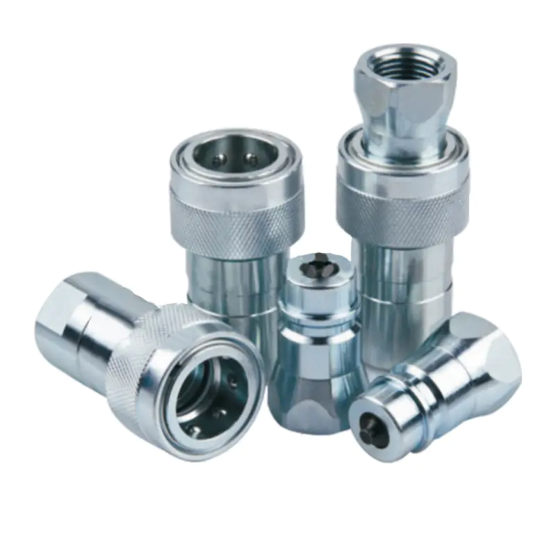
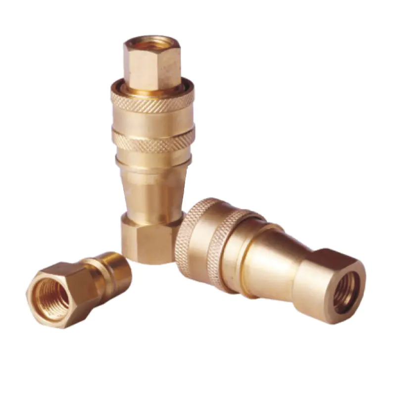
Flow Path Geometry and Airflow Resistance: The internal flow path geometry of a Pneumatic Quick Coupling plays a fundamental role in determining airflow resistance, which directly influences pressure drop and overall flow efficiency within a pneumatic system. A well-engineered flow path incorporates smooth contours, gradual transitions, and streamlined passages that allow compressed air to move with minimal disruption. When air flows through a coupling with sharp edges, sudden directional changes, or abrupt reductions in cross-sectional area, turbulence is generated, increasing frictional resistance and causing energy loss. This energy loss manifests as a pressure drop between the inlet and outlet of the coupling, which reduces the effective pressure available to downstream components. As a result, the compressor must operate at higher capacity to compensate for these losses, increasing energy consumption and operational costs. Therefore, optimized flow path geometry ensures reduced turbulence, stable pressure delivery, and improved pneumatic system efficiency.
-
Effective Flow Area and Cross-Sectional Design: The effective internal diameter and cross-sectional configuration of a Pneumatic Quick Coupling significantly affect its ability to handle compressed air flow efficiently. A coupling with insufficient internal flow area creates a restriction that increases air velocity and frictional losses, resulting in higher pressure drop and reduced system performance. This restriction can act as a bottleneck within the pneumatic circuit, limiting the airflow supplied to actuators, valves, or tools and causing delays in system response. Conversely, an adequately sized cross-sectional design allows air to flow at optimal velocity while maintaining stable pressure conditions. Engineers must carefully match the coupling’s internal dimensions with the required system flow rate, ensuring compatibility with the pneumatic network’s operating conditions. Proper cross-sectional design improves volumetric efficiency, reduces unnecessary energy loss, and supports consistent operation of downstream equipment under varying load conditions.
-
Surface Finish and Internal Roughness: The quality of the internal surface finish in a Pneumatic Quick Coupling is a critical factor influencing frictional resistance and flow efficiency. Smooth internal surfaces reduce boundary layer resistance and allow compressed air to move through the coupling with minimal energy loss. In contrast, rough or poorly machined surfaces increase friction between the airflow and the coupling walls, generating turbulence and causing additional pressure drop. Surface irregularities can also promote the accumulation of contaminants, moisture, or particulate matter, further restricting airflow and degrading performance over time. High-precision manufacturing processes, including fine machining and surface treatment techniques such as polishing or protective coatings, help maintain low surface roughness and consistent airflow characteristics. Maintaining smooth internal surfaces ensures efficient air transmission, reduces system energy requirements, and extends the operational life of the pneumatic components.
-
Valve and Obstruction Design: Many Pneumatic Quick Couplings incorporate internal valve mechanisms that automatically control airflow during connection and disconnection, and the design of these components has a significant impact on pressure drop and flow efficiency. If the valve structure obstructs the airflow or introduces complex internal passages, it can create resistance that limits flow capacity and increases pressure loss. Efficient valve designs are engineered to open fully upon connection, providing an unobstructed flow path and minimizing interference with the moving air. Streamlined valve components and optimized positioning reduce turbulence and allow compressed air to pass smoothly through the coupling. Additionally, the responsiveness and sealing effectiveness of the valve influence how quickly full flow is established, which is essential for maintaining system performance. Proper valve design ensures reliable air control while preserving efficient airflow and minimizing energy losses.
-
Flow Direction Changes and Turbulence Generation: The number and severity of directional changes within the internal structure of a Pneumatic Quick Coupling directly influence turbulence formation and associated pressure losses. When compressed air is forced to change direction abruptly, kinetic energy is dissipated through the formation of vortices and eddies, reducing the effective energy available for useful work. Excessive turbulence not only increases pressure drop but also causes unstable airflow conditions that may negatively affect the performance of downstream pneumatic components. Well-designed couplings incorporate gradual curves and optimized flow channels that guide air smoothly through the system, minimizing directional disruptions. By reducing turbulence and maintaining steady airflow, the coupling improves pressure stability, enhances system responsiveness, and ensures efficient transmission of compressed air energy throughout the pneumatic circuit.
Industrial Blog
How does the internal flow path design of a Pneumatic Quick Coupling affect pressure drop and flow efficiency?
28
Mar
Mar