
The internal diameter of a Hydraulic Quick Coupling is one of the most critical factors affecting flow efficiency. Larger diameters allow a higher volumetric flow rate with minimal resistance, ensuring that hydraulic fluid can pass through the coupling with low pressure drop. This is particularly important in systems requiring high flow rates, such as industrial machinery or mobile hydraulics, where inadequate flow can slow actuator response and reduce operational efficiency.
Industrial Blog
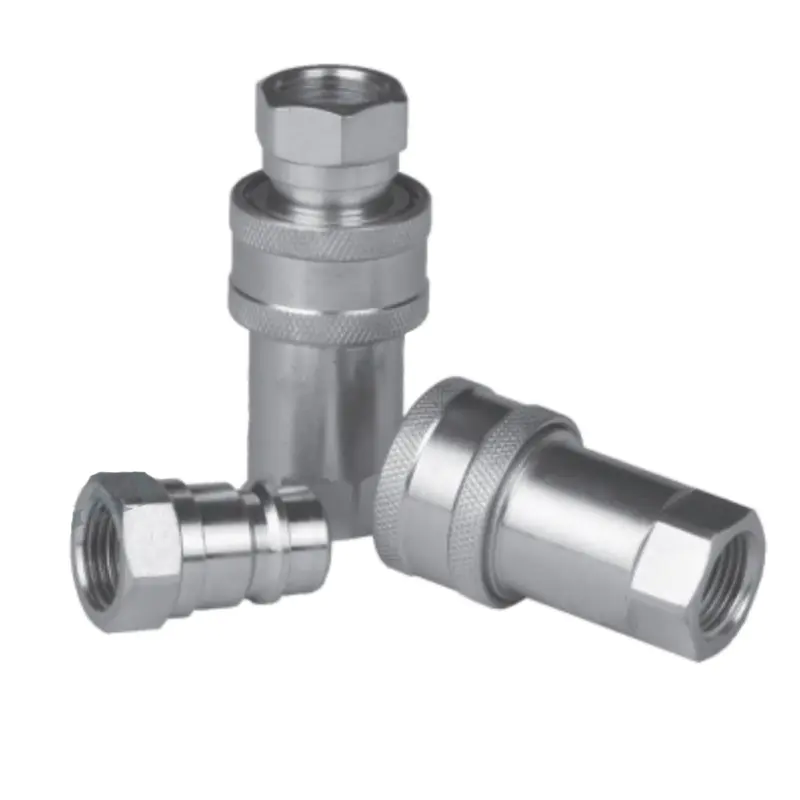
How does the design of the locking mechanism in double shut-off hydraulic quick couplings ensure secure coupling even under high pressure and vibration?
28
Mar
Mar
The two-stage locking mechanism is an integral feature of double shut-off hydraulic quick couplings that provides enhanced security during coupling and uncoupling processes. The first stage involves a valve or sleeve system that prevents fluid from flowing as the coupling is being disconnected, ensuring no fluid leakage occurs during the connection or disconnection process. The second stage involves the mechanical locking feature, which locks the coupling components in place once the coupling is connected.
Industrial Blog
How does the design of a Pneumatic Quick Coupling impact air leakage and overall pneumatic system efficiency?
28
Mar
Mar
Sealing Mechanism Design and Leak Prevention: The sealing mechanism of Pneumatic Quick Coupling is one of the most critical design features influencing air leakage and system efficiency. High-quality couplings typically incorporate precision-engineered sealing elements such as O-rings, elastomeric seals, or flat-face seals that create a tight interface between the plug and socket. The effectiveness of these seals depends on factors such as material compatibility, compression force, and resistance to wear under repeated connection cycles.
Industrial Blog
How does the internal flow path design of a Pneumatic Quick Coupling affect pressure drop and flow efficiency?
28
Mar
Mar
Flow Path Geometry and Airflow Resistance: The internal flow path geometry of a Pneumatic Quick Coupling plays a fundamental role in determining airflow resistance, which directly influences pressure drop and overall flow efficiency within a pneumatic system. A well-engineered flow path incorporates smooth contours, gradual transitions, and streamlined passages that allow compressed air to move with minimal disruption. When air flows through a coupling with sharp edges, sudden directional changes, or abrupt reductions in cross-sectional area, turbulence is generated, increasing frictional resistance and causing energy loss. This energy loss manifests as a pressure drop between the inlet and outlet of the coupling, which reduces the effective pressure available to downstream components.
Industrial Blog
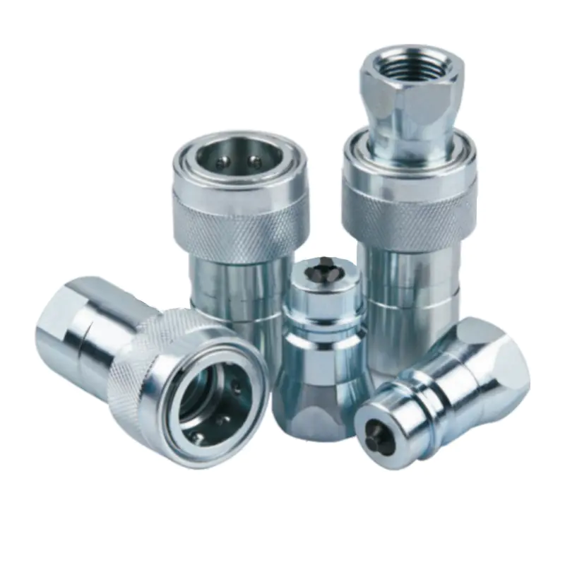
How does the internal design of a hydraulic quick coupling affect pressure drop, flow turbulence, and overall system efficiency?
28
Mar
Mar
Influence of internal geometry on pressure drop: The internal configuration of a hydraulic quick coupling is a primary determinant of pressure loss in a hydraulic system. Constrictions, abrupt changes in diameter, or sharp edges inside the coupling create localized friction and energy dissipation, resulting in a measurable pressure drop across the component. High-pressure drops reduce the effective hydraulic pressure delivered to actuators, limiting force output, reducing system responsiveness, and potentially causing inconsistent operation in high-demand applications such as mobile machinery or industrial presses.
Industrial Blog
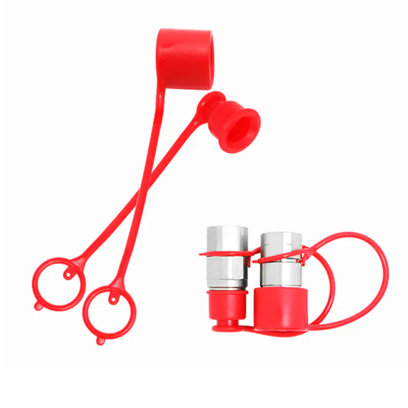
How does the design of a hydraulic fitting dust cap prevent contamination in hydraulic systems?
28
Mar
Mar
The primary function of a hydraulic fitting dust cap is to prevent dirt, debris, and moisture from entering hydraulic connections. By forming a secure seal over unused fittings, dust caps maintain system cleanliness, which is critical for avoiding contamination-related failures. Proper use of dust caps can reduce hydraulic component wear and system downtime by up to 40%.
Industrial Blog
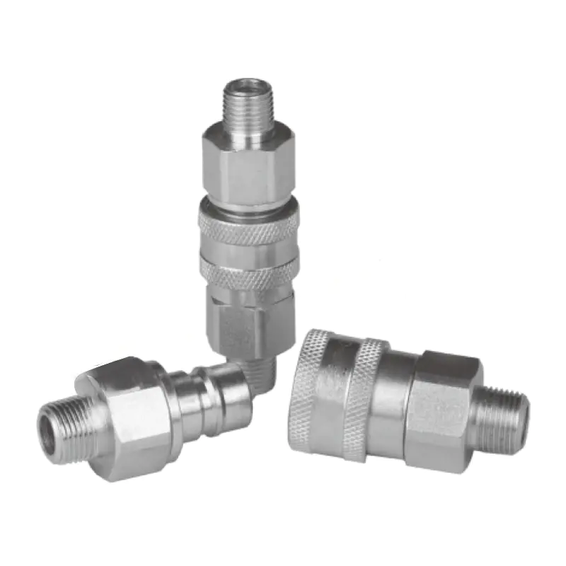
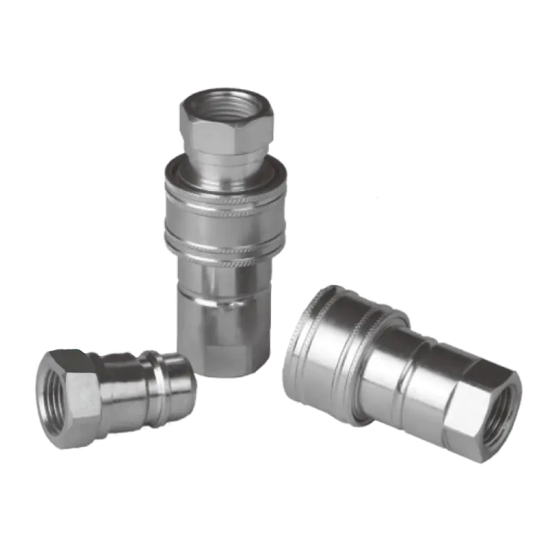
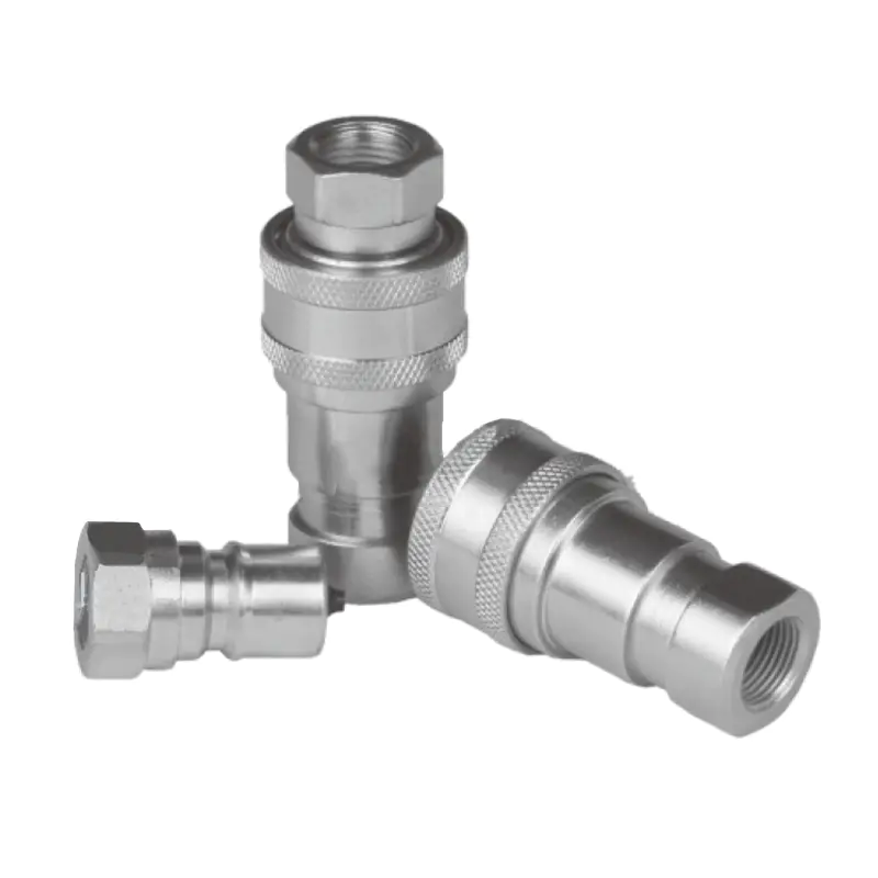
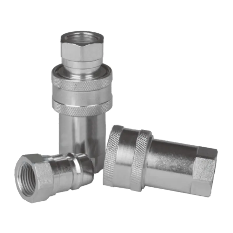
How does the Stainless Steel Quick Coupler perform in environments with extreme temperatures or pressures?
28
Mar
Mar
The Stainless Steel Quick Coupler performs exceptionally well in environments with extreme temperatures and pressures. Designed with high-grade stainless steel alloys and precision-engineered seals, it maintains operational integrity in temperatures ranging from -196°C to 400°C and pressures up to 1,500 PSI without leakage, deformation, or failure.
28
Mar
Mar
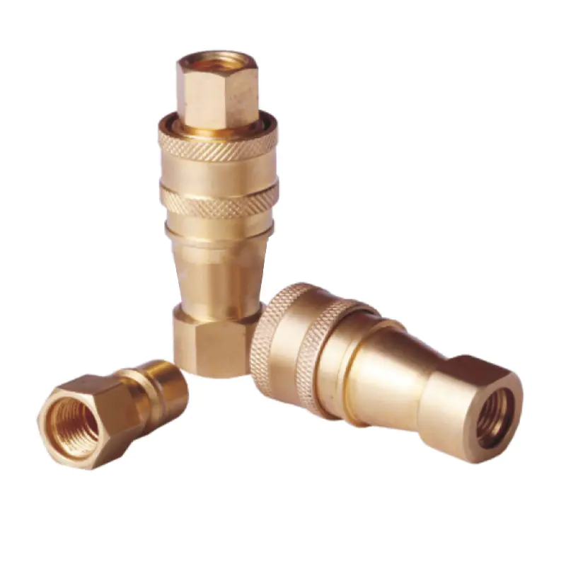
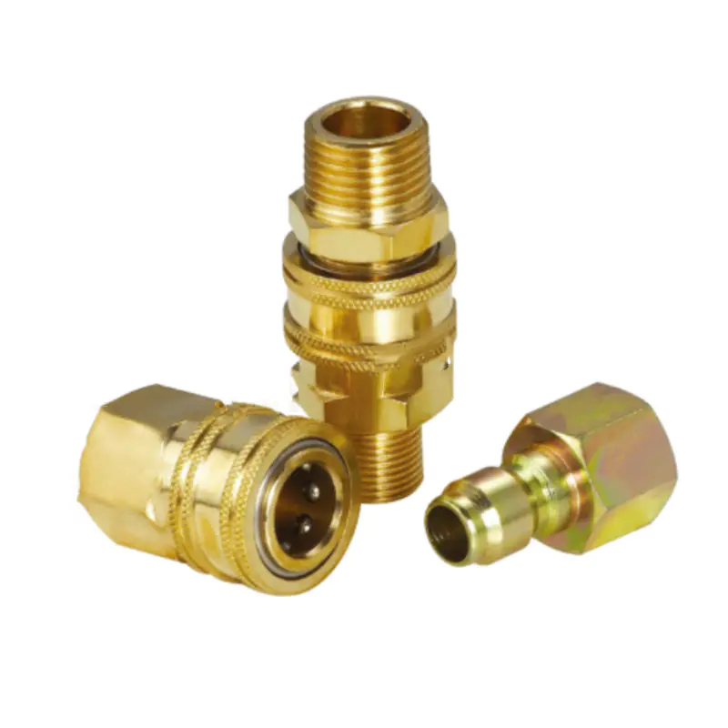
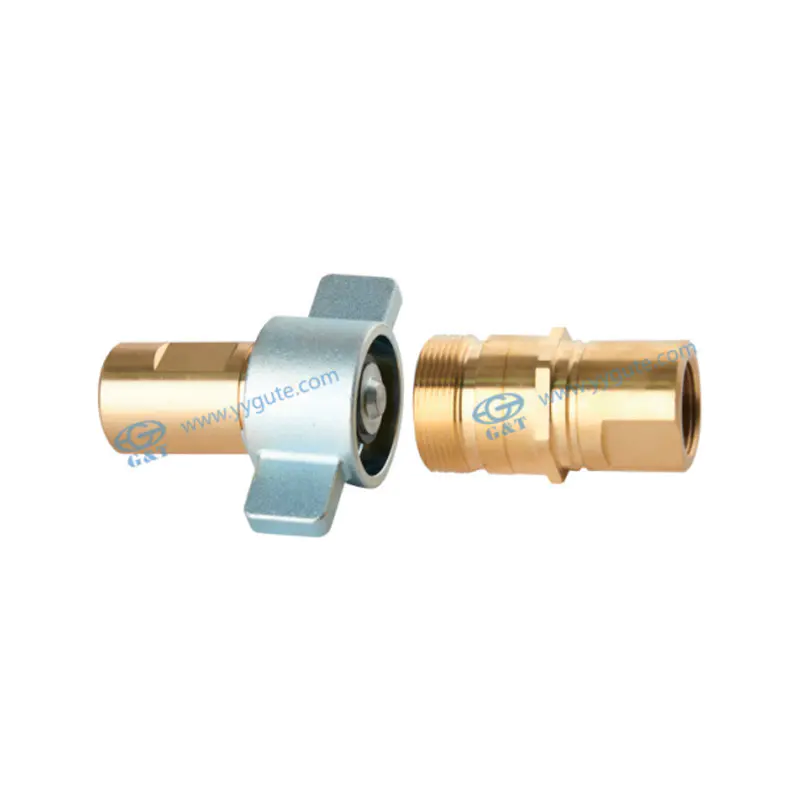
The Brass Quick Coupler can be used for both air and water applications. However, its suitability for these two mediums depends on various factors such as pressure, temperature, and material compatibility. While brass is a robust material offering durability, its performance can be influenced by the specific demands of air or water systems. In many cases, it is the perfect choice for systems where both air and water are handled under moderate pressure ranges.
Industrial Blog
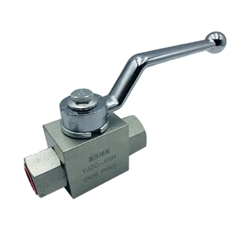
How does the High Pressure Ball Valve handle pressure surges or water hammer conditions in pipeline systems?
28
Mar
Mar
The High Pressure Ball Valve handles pressure surges and water hammer conditions primarily through its robust structural design, tight sealing mechanism, and rapid shut-off capability. These valves are engineered to withstand sudden spikes in pressure—often exceeding normal operating pressure by 1.5 to 3 times—without deformation or leakage. Their full-bore or reduced-bore configurations, combined with high-strength materials and reinforced seats, allow them to absorb transient hydraulic shocks effectively while maintaining system integrity.